Have you noticed that some lights can have water in them and not trip the GFCI? If the light has a built in transformer, then this could happen. This video explains why.
Clint Combs's Posts (14)
Sort by
I was called out to a MasterTemp pool heater that was knocking and shutting off after running for just a couple of minutes. I assumed I might have to replace the unitherm governor, but found that the header was plugged with flakes of white scale which seemed to have a rounded green side like it used to be coating the inside of the copper heat exchanger. There were 1 to 2 cups of this scale. After flushing it out, the heater worked fine again and the heat exchanger looked to be in good condition.
Any ideas as to why it formed in the heater and what caused it to break free (seemingly in a short time) from the tubes and move into the header?
It is possible that the scale was simply the result of scaling water (high pH, Alkalinity, etc.), but, I also wonder if venting is an issue. The vent starts small, and increases (see picture). Notice that there is corrosion the elbow that is right below the increaser indicating that condensation formed there. Since exhaust gases cool when the pipe volume is increased, this cool / condensing exhaust gas might have sat in the pipe (rather than rising) and created a "thermal plug" that obstructed the flow of the exhaust out of the heater. This would have caused more heat to remain in the heater and be transferred to the water. This would inadvertently raise the efficiency of the heater beyond its normal level. I know that an efficiency greater than 84% would result in the formation of acidic condensate on the outside of the exchanger, but would it also promote the formation of scale in the exchanger? If so, why?
Does anyone else see it as problematic that whenever a bill comes up that proposes licensing in the pool industry that the very organizations that make money from the licensing process are always the most vocal promoters?
We hear rhetoric like, “Without licensing standards, there are no requirement for pool techs to attend classes and learn about new laws and regulations.” While it is true that without a requirement there is no requirement, it does not follow that without standards pool tech won’t keep current in their field.
I just spent three days taking classes at the Western Pool and Spa show and before that spent two days in a training seminar with Pentair. No one required me to do this. But I did it because I am always looking for ways to step up my game and I always learn something at the seminars.
Licensing to me seems like the failed “no child left behind” education policy. It is focused on the minimum requirement rather than excellence. It treats pool techs like defiant children who don’t want to do anything, rather than responsible adults who want to better themselves.
Especially problematic is that these bills all tacitly assume that education itself is irrelevant until some authority like the trade organizations that promote these bills collect a fee from you and certify you. This to me is an insult to education. It turns it into a commodity.
A further assumption seems to be that unlicensed techs are more dangerous than licensed techs. While this statement may be true, it is a quantifiable statement and should be quantified before being thrown around as fact and as the reason to enact yet another law that impacts our industry.
Yesterday I installed a Pentair SunTouch with an Intelliflo VS+ pump.
This is a nice simple setup that allows the pump to change speeds depending upon whether it needs more power to send the water up to the solar panels on the roof or more water to satisfy the flow demands of a gas heater or the spa jets. So, for a basic pool & spa system with solar it is nice and simple.
However, there is a bit of a learning curve and some surprises in store for those not used to the SunTouch. The first is: HOW DO I STOP THIS THING?
On most pools, it is easy to turn off the pump to clean the basket. With the old mechanical time clocks, you just have to flip the switch in the timer. With the EasyTouch, IntelliTouch, Jandy Aqualink, and Jandy PDA you just press one button to switch fromAuto mode to Service mode and the pump goes off.
Well, the same principle applies with the SunTouch, but it takes quite a few button pushes to get there. To turn the pump off if a schedule has turned it on, you need to switch from Auto to Service.
On the SunTouch:
1. Press Menu button 14 times until you see “Service Mode 14/14.”
2. Right arrow into the service menu.
3. Use up or down arrow to change from Auto to Service.
4. Press right arrow to select Service mode.
5. With the pump in Service mode, clean the pump basket or filter as needed.
6. To restart, repeat steps as needed this time changing from Service to Auto mode.
a. In addition to Service and Auto, there is also a Time Out mode. It is like the Service mode, but it will
automatically switch back toAuto after a 3 hour delay.
This blog post is about the chemistry of combustion, not the chemistry of the pool and spa water that is being heated.
Combustion:
Pool and spa heaters burn either natural gas—typically methane (CH4) or propane (C3H8). Since both of these fuels are made up of the same basic stuff—carbon and hydrogen, just in different proportions, the combustion reactions are going to be similar. For the sake of simplicity, I will just focus on the combustion of natural gas.
Ideally, the combustion reaction is as follows:
CH4 + 2 O2 → CO2 + 2 H2O (ΔH = −891 kJ/mol (at standard conditions))
In other words, the combustion (i.e. oxidation) of natural gas yields carbon dioxide, water vapor, and a lot of heat.
Water vapor—a common byproduct and its disposal problem:
As noted above, one very common byproducts of combustion is water vapor: Put your hand a foot our two above a heater that is running and it will feel wet from the hot exhaust. If the heater’s combustion chamber and exhaust vent are hot enough, this water will remain vaporized long enough to exit the heater.
Interestingly, one of the key reasons that double wall vent pipe is recommended is not that it keeps the outside of the pipe cooler and thus safer, but that it keeps the inside hotter. A hot inner pipe improves its natural drafting ability due to the fact that hot air rises. The double wall pipe acts as insulation and the exhaust hot. The hot exhaust keeps the water in vapor form as it travels through the vent pipe. If you choose to use single wall vent pipe instead, the exhaust will lose its heat through the single wall pipe. As a result the exhaust will cool and the water vapor inside will condense while still in the pipe. This condensation explains why single wall vent pipe rusts more than double wall pipe.
Low gas volume—a first obstacle to water vapor disposal:
If the volume of gas available to the heater is insufficient to provide for the minimum requirements, the heater may still light, but if it does, it will not burn as hot as it should. As a result, some of the water vapor in the exhaust will cool enough to condense before it rises completely out of the heater. This results in excessive rust-causing moisture remaining in the heater. Low gas pressure also produces an excessively yellow flame that emits a black soot that will stick to and eventually build up on the heat exchanger. Over several months or years, this soot will eventually block the exit of the exhaust. It will also trap excess heat in the heater causing it to become more efficient than it was designed to be. This efficiency is not as good as it sounds as the heater is destroying itself in the process (more on this later).
Excessive water flow—a second obstacle to water vapor disposal:
Heaters are designed with a specific water flow in mind and have automatic valves that control the flow of water through the heater. Some of the better heaters will have two types of these valves. One type of valve is spring operated and is designed to produce a consistent flow of pool water through the heater despite the heater being used with a variety of pump sizes and with different amounts of restrictions due to the filter.
In addition to the pressure operated valve, there is often a thermally controlled valve that is designed to provide a constant heat exchanger temperature. If this thermally controlled valve malfunctions (or is not part of a particular heater’s design—it is absent from the Series One Laars, the Laars Lite, and the new Universal Forced Draft Hayward (UFD)), then the temperature of the heat exchanger will vary as the water heats up. If the initial water temperature is low, so too will be the temperature of the heat exchanger. And, if the heat exchanger is too cool, the water vapor from the combustion will condense on it and “rain” back into the heater. If you see a rusted burner tray on a Laars, this is probably the cause. Hayward claims that their new UFD heater is built so well, that this condensate “rain” will occur, but will not damage anything.
More than 84% efficient—a third obstacle to water vapor disposal:
Have you ever wondered why even some of the best heaters are “only” 84% efficient? Have you wondered why there is a major price jump upwards between these commonly used heaters and the rarely used “high efficiency” heaters? There is a good reason for this and it is all about the disposal of combustion water vapor.
As I said above, a heater’s exhaust needs to remain sufficiently hot for it to keep the combustion water vapor from condensing inside the heater. If the heater transfers more than 84% of its heat to the pool water, the exhaust becomes too cool to carry away this water as vapor. As a result, the water vapor from the combustion cools, condenses, and “rains” back into the heater. The condensing water (H2O) combines with carbon monoxide (CO) to form carbonic acid (H2CO3). As a result, the condensate from a high efficiency heater has a pH that is typically in the 3.5 to 6.0 range.
Efficiency in excess of 84% can come about by design—as in the Laars Hi-E2—or due to an unintended blockage that occurs within a standard heater. Heaters like the Hi-E2 that are designed to be highly efficient are manufactured with stainless steel burners and combustion chamber components to withstand the acidic condensate. Additionally, they have condensate traps and neutralization basins. These basins utilize limestone to neutralize the acidity of the condensate so that it can safely be disposed.
Standard heaters can inadvertently become highly efficient as the result of low gas volume—measured as low pressure with a manometer. Insufficient gas volume produces a flame that emits soot. This soot sticks to the fins of the heat exchanger thereby blocking the passage of exhaust gases. In blocking the exhaust, the soot slows the flow of the exhaust allowing it extra time to transfer heat to the water—thereby resulting in a highly efficient heater. Unfortunately, heaters that become highly efficient in this manner are not designed to handle the acidic condensate. As a result, the acidic condensate attacks the metal components and results in excessive rust and corrosion. These unintended high efficient heaters have only a short life left before they destroy themselves.
Formaldehyde—an occasional nasty byproduct of combustion:
There is one particularly nasty byproduct of combustion that sometimes occurs: Formaldehyde (HCHO, also written H2CO) is one of these. Typically, formaldehyde is a short lived byproduct that quickly oxidizes in the extreme heat of the combustion chamber to form carbon monoxide (CO) and water vapor (H20). The carbon monoxide (CO) then oxidizes into carbon dioxide (CO2). Sometimes, however, if conditions are wrong—if the combustion chamber is not hot enough—the formaldehyde doesn’t get oxidized and exits the heater as a smelly, eye-irritating gas. This mostly happens on low NOx heaters.
The reason for this is that low NOx heaters have blowers that are designed to lower the temperature of combustion—thereby reducing the formation of oxides of nitrogen (NOx) that are known to form in small quantities at certain temperatures. The fans lower the combustion temperature and thus lower the quantity of oxides of nitrogen (NOx) that are produced. Occasionally, some of the gas orifices on these heaters become clogged with spider webs. When this happens, only a fraction of the intended gas actually gets to the burners. As a result, the temperature within the combustion chamber is reduced even further. At this lower temperature, the formaldehyde doesn’t oxidize as it normally does in the combustion chamber and exits the heater. This results in a heater that smells particularly foul and will cause eye irritation. This problem is particularly prone to occur on low NOx style RayPak heaters. See my YouTube video of how to correct this problem.
Conclusion:
Understanding the chemistry of combustion can help when trouble-shooting a heater. The presence of rust—and its location—is a major clue never to be overlooked, so too are noxious formaldehyde odors and sizzling sounds caused by condensate “raining” down on the burners.
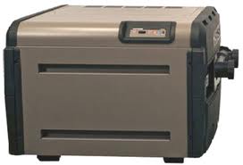
 |
| Hayward H-series Heater |
 |
| Orifice blocked by spider web next to open (good) orifice |
 |
| Burner with openings blocked by rust |
The rust came about because the heater is "condensing." This happens when condensation forms on the heat exchanger (located directly over the burners). The condensation then drips down onto the burners. You can often hear the effects of a condensing heater. It will sound like water being flicked onto a hot skillet.
The way to fix the problem is to replace both bypass valves in the inlet/outlet header. There is one bypass that operates on pressure and one that relates to temperature. Either could cause this problem and since it takes a good deal of labor to get in there, it is better to replace both. Then, after fixing the cause, fix the damage by replacing as many burners as necessary.
Even the newest versions of the Hayward / Goldline AquaLogic controller (2.85) are not setup to select different speeds on the Intelliflo Pump.
It is possible, however, to get the two to work together using the first generation Pentair IntelliComm.
Programing the Pump:
First, set up four distinct speeds on the pump. This is straight forward on the old style 4 X 160. If using a newer menu driven pump set up the speeds in the External Control menu.
Strategy for setting up the speeds:
When using a variable speed pump with a control system, be aware that the controller will often call for more than one speed at a time. The IntelliComm resolves such conflicts by switching to the highest speed number (1-4). Depending upon how these are set, this may or may not actually be a faster speed. Indeed, in once case (if you follow my strategy below), it will not be a faster speed.
Speed 1 will be your default speed that comes on when the pump is turned on. Set this speed to an appropriate rate to operate the automatic pool cleaner (if one is present).
Speed 2 will be your low/economy speed. If both speed 1 and 2 are activated at the same time, the pump will run at the slower speed 2.
Speed 3 will be used to ensure that your heater has adequate flow should the heater come on while the pump is running in low speed (speed 2). If both speed 2 and 3 are activated at the same time, the pump will run at the faster speed 3.
Speed 4 will be used for the spa jets. This will ramp up the pump speed to its highest setting.
Programming the Controller
Setting up your time clocks:
When you set your timers, you will set the filter pump for the total time that you want the pump to run. This should be about 12 hours (8am-8pm).
Within those hours, you will set a time to run the low speed. You could go into the Configuration Menu and set it up as a two speed pump and use auxiliary 1 or 2, but I will assume that those are already being used for other things and are thus not available. The better alternative is to use Valve 3. I recommend programming Valve 3 to operate the low speed during the middle of the day. (I recommend 10am-7pm.) This way the pump only runs on high for 2 hours in the morning and 1 hour in the evening. During the peak usage of mid-day, the pump runs on low for 9 hours. Running the pump on low for 9 hours will use about the same amount of energy that it would to run it on high for 1 hour, but by running it on low, you have continuous filtration and chlorination when the sun is up and algae growth is more active. The longer run time for your chlorinator prevents dips and spikes in your chlorine level.
Wiring the IntelliComm
Wire the 240v power supply for the variable speed pump directly to a breaker. You do not want to use the filter pump relay for this. (It will be used to activate speed 1).
Power the IntelliComm with 110v (terminals 1&2). I recommend using the same breaker that powers the Aqualogic board.
Rewire the high voltage side of the filter pump relay to send 110v to terminals 3&4 of the IntelliComm. This will call for speed 1 (high speed).
Plug a valve actuator cord into the Valve 3 socket. Connect the black wire to terminal 5. Connect either the red wire or white wire to terminal 6. Use whichever one has power when Valve 3 is activated. This will activate your speed 2 (low speed).
Inside the heater connect one conductor or a two conductor thermostat cord to the low voltage ground side of the transformer and the other conductor to a place that has 24vac when the heater calls for heat. Connect this thermostat wire to terminals 7&8 of the IntelliComm. This will activate speed 3 (heater speed).
Splice into the wire going to either the suction valve or the return valve. If you would like to ensure a strong waterfall if the spillover feature is active, then splice into the wire for the return valve. Again, as before, you will connect the black wire to terminal 9 and connect either the red or white (whichever has power when the spa is on) to terminal 10. This will activate speed 4 (spa jets).
Finally, attach the yellow wire on the variable speed pump cord to terminal 11 and the green wire to terminal 12. Plug the other end of this cord into the data socket on the variable speed pump.
Using the system
Once it is programmed, you can forget that it has different speeds. Just use it as usual and the pump will switch to the appropriate speed without the user having to think about it.
I ran across an interesting problem earlier this week. I was working on a newer style Hayward UFD (Universal Forced Draft) heater.
It would try to light, then--after three attempts--it would fail and give an IF (Ignition Fail) error.
Many problems can cause this error:
- A bad flame sensor
- A bad ICB (Integrated Control Board)
- A bad HSI (Hot Surface Igniter)
- When there is first a call for heat, the ICB sends power to the HSI. If the current draw of the HSI is sufficiently out of range, the board will immediately trigger an IF error and the start up sequence will stop at that very point.
- If the HSI passes this initial self check, then the fan will come on and hopefully activate a vacuum switch thereby proving to the ICB that the fan is working. At this point, the HSI will start heating up. If you measure the current draw of the HSI using a clamp-on amp meter that is placed around one of its wires, you will initially see it draw about 3 amps, then slowly draw less and less current until it is drawing a pulsating 1-1.5 amps (the needle will actually pulsate up and down).
- The gas valve will then open for 4 seconds and the HSI should ignite the gas.
If the heater still fails to light it could be for several remaining reasons:
- Spider webs could be blocking the flow of gas to the burners. It is quite common for a spider to build a web that will clog up the gas orifice that supplies gas to the burners. These must be unscrewed from the manifold for cleaning. Poking a hole in the spider web and pushing it back into the manifold with a wire is a short term solution at best and at worst, will result in a roll out hazard later on.
- It is also possible that the heater fails to light because the gas valve isn't opening. Use a manometer on the manifold side of the gas valve to confirm that the gas valve opens and is supplying the proper amount of gas for combustion.
- It is also possible that you STILL have a bad igniter. Even though the igniter passed its self test and even though it draws approximately the correct amount of current as shown using the clamp-on amp meter, and even though it gets hot the the touch, it may still not be getting hot enough to ignite the gas. I found this to be true earlier this week. The HSI that was in the heater was simply not getting hot enough. I checked the resistance of this igniter against that of a new igniter. The existing (and bad) igniter had about 37 ohms of resistance. The new (and good) igniter read had about 15-16 ohms of resistance.

Some years ago with the advent of Low NOx (low nitrous oxide) heaters, many manufacturers switched from using pilot lights to ignite the burners to using direct ignition from a red hot glowing hot surface igniter. These work much like the electric heating element does on a stove or toaster. Just like a toaster can light your toast on fire, these hot surface igniters can light gas on fire.
Hayward's first shift away from a pilot light was to use direct spark ignition of the main burners. They then switched to using the same type of fragile hot surface igniters Pentair, StaRite, and Jandy still use.
These fragile igniters are made of Silicone Carbide. This material is very brittle. Replacement ones come packaged in foam rubber to prevent breakage during transport--and many of them still break during shipping. Installing them is a bit like playing the game that old game called Operation--one careless move and the igniter is broken.
Hayward chose to address this problem by switching to a more robust igniter made of silicone nitride. During their technical training seminars they show Power Point slides where these igniters have been hammered through a 2x4. This strenght is impressive for those of us familiar with the fragile-as-glass silicone carbide igniters. Nevertheless, despite their strength, they still fail. And, when they do fail, they can fail in ways that show no visible signs of failure. Such failure makes troubleshooting a little harder at times.
First, there are some things you should be aware of before you start programming:
• The Filter Pump button will only work in the Auto mode. It will not turn the pump on in either Service or Timeout mode. For those familiar with EasyTouch controllers and single speed pumps, this is unusual. For this reason, it is nice to set up an Auxiliary button to turn the variable speed pump on to a speed that is appropriate for vacuuming or running an auto cleaner. Your pool service person will need this.
• The pump will often be told conflicting directions as to what speed it should run at. For instance, a program may call for one speed and the heater may call for a different speed. If there is a conflict between two different speeds, the pump will always run at the higher speed.
Conceptual programming strategies:
• You will want to program the “Pool” to run at the slowest speed that you want the pool to run at. If you do this, you will not need to set up an additional “low speed” speed/schedule.
• You will want to set up a “Feature” (Feature 1—for instance) to run at a medium to high speed. At scheduled times during the day, this feature will ramp up the pump to a sufficient speed to operate an auto cleaner for a couple of hours a day. You will set the time for this in Schedules and the speed in the Intelliflo menu.
Programming Steps:
To avoid confusion, start by assigning circuit names:
- Label your auxiliaries (pool light, spa light, blower, etc.)
- Name one auxiliary “Manual Clean.” (Use one that is not connected to a relay or one whose relay is not being used.) In a later step, you will assign a pump speed to this auxiliary that appropriate for vacuuming. Later, (in Schedules) you will also set this up to operate as an “egg timer.” You or your service person will be able to select this speed (by pressing its Auxiliary button when in the Auto mode) the pump will then ramp up to a speed appropriate for vacuuming. This is very useful for service personnel. Since this will be set up as an “egg timer,” the pump will revert to its normal settings after the egg timer has expired.
- Name one Feature circuit “High Speed.” Later, (in Schedules) you will program this to operate once or twice a day to ramp up the pump to run an auto cleaner.
Assign the circuit types:
- Assign the Manual Clean the generic type. You will be tempted to assign it the “Master Cleaner” type. Resist this urge, as doing so will result in a delay before the pump ramps up to your desired speed.
- Assign the “High Speed” the generic type.
Setup your Schedules:
- Set a schedule for the “Pool” to run for about 12 hours a day. Remember that this will be your lowest (and most economical speed).
- Set a schedule for the Feature Circuit that you have labeled “High Speed.” Set this to come on one to two hours once or twice a day. For small pools, one to two hours in the morning is enough. For larger pools or pools in windy areas, it may need to run twice a day (once in the morning and once in the evening). Your utility company prefers that you set this to run during off peak hours. This speed can either be programmed within the time set for the “Pool” speed (the lowest speed) or outside of that time. If it is programed within the “Pool” time, the conflict will be settled by the pump running at the higher speed that you labeled “High Speed.”
- Set up the Auxiliary that you labeled “Manual Clean” to work as an egg timer. You do this in the Schedule menu. I recommend setting the count down time between 3 and 8 hours depending upon the size of the pool and usage. You pool service person can use this speed to ensure that the water filters after chemical additions or use this for vacuuming or other clean up purposes.
Assign the Speeds in the Intelliflo menu under Settings:
- Assign the “Pool” speed the slowest setting that you want the pump to run (1200-1900 rpm). Make sure that this speed is sufficient to activate the flow switch on a chlorinator.
- Assign “Manual Clean” and “High Speed” a medium speed that runs the auto cleaner at a good pace (2400-3100 rpm).
- Assign the “Heater” a medium speed. Tying this speed to heater operation will ensure that the heater always has adequate flow, even if it happens to be turned on during a time in which the pump is running at a slower speed that would not otherwise give it enough flow.
- Assign the “Spa” the highest speed (3100-3450 rpm). When the valves are switched from pool to spa, the pump will ramp up to this highest speed so that the jets will give the expected action.
The White House has two swimming pools. The most noticeable one is behind the West Wing surrounded by trees and featuring a changing cabana. This pool was built during the Ford administration. President Ford’s
son used it for scuba lessons. Barbara Bush also loved this pool, though it is
reported that she once saw a rat swimming in it.
But there is an older pool in the White House that is not so easily to find. It was built in 1933 during FDR’s tenure and used for his therapy swims. It was later used by Truman, who reportedly swam with his glasses on and by JFK who used it nearly twice a day.
President Nixon had this original pool drained and a floor laid over it. That floor serves as the floor of the White House briefing room. The pool itself, however, remains intact.
--Based on the article, “The president’s other pool,” by Peter Grier in The Christian Science Monitor, July 19, 2010.